MBJ Controller Portfolio
MBJ offers a versatile controller portfolio matched to MBJ lighting fixtures for precise and powerful control.
- Integrated Controller:
Versatile internal -s controller for MBJ standard lights with four operating modes and high efficiency for low heat generation. - Cable Controller:
The popular -s controller as a cable-integrated version, e.g. to retrofit standard lights without an internal controller (-x version).
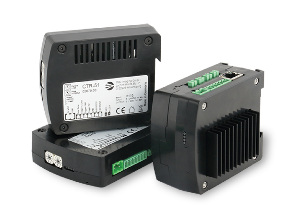
External controller CTR series:
- CTR-50 for precise brightness control
The current-regulated controller is designed for precise and permanently stable brightness control of large lighting devices, e.g. from the Flex series.
- CTR-51 for powerful flashing
The voltage-regulated CTR-51 enables very short flashes in the µs range with very high currents for maximum brightness output at high test speeds. - CTR-52 for versatile 4-channel control
The CTR-52 can control both current-regulated brightness and voltage-regulated powerful flashing for 4 independent channels.
All external controllers are also suitable for the operation of external lighting. The compatibility of the specific external lighting must be checked (esp. LED U/I working point).
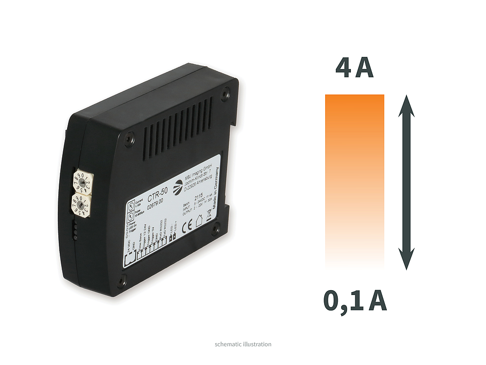
CTR-50
Continuous light with precise brightness control
The CTR-50 ensures constant brightness via direct and thus precise current control, which enables consistent recording quality. A digital control allows a very fine gradation of the brightness.
- For stationary test objects
- Stable and fine brightness control
- Operation:
- Steady light
- Analoge and digital brightness control
- Switched continuous light
- Simple flash light applications
- Simple setup via rotary control or RS232 interface
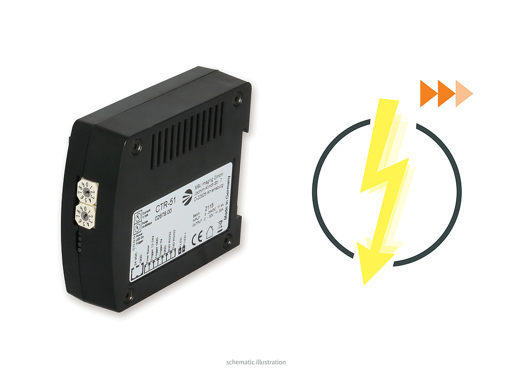
CTR-51
Powerful flash/boost mode
The CTR-51 enables voltage-regulated extremely short and light-intensive flashes in boost mode that are unparalleled, especially in this price range. The controller is developed for very high-frequency shots, which can thus be made with sufficient light intensity. The electronic enables minimal latency times (as short as 1 µs).
- Image capture of fast moving objects
- Flash times from 1 µs to 100 ms
- Up to 30 A boost current
- Simple setup via rotary control or RS232 interface
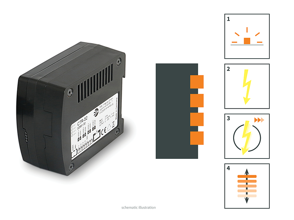
CTR-52
All-round talent
The CTR-52 is a real all-round talent and that over up to 4 channels. Current-controlled brightness levels can be set precisely, while the voltage control enables powerful flashing. With the CTR-52, 4 channels can be controlled independently or coupled, allowing even complex test tasks to be completed safely.
- Complex test tasks
- Up to 4 channels with different operating modes
- Steady light
- Brightness control
- Flash & strobe mode
- Modern, simple and versatile control via Modbus. Phython scripts are available for easy integration into your own software.
Plug 'n' Play
Internal controller
The internal controller offers plug'n'play for particularly efficient integration into your test systems. That's why all MBJ standard illuminators are available with the versatile internal -s controller. Set-up guide
Advantages:
- Cost savings
No additional external LED controller is required - Low heat generation
The use of a modern LED switching controller with high efficiency results in low heat dissipation - Fast
An additional microcontroller constantly monitors the trigger input - Versatile
The 4 operating modes are sufficient for most of the applications in image processing - Flexible control
Trigger control is possible directly from the camera, a proximity sensor or a PLC
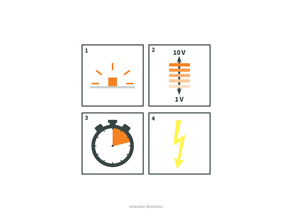
The -s controller offers 4 operating modes with which a majority of all inspection tasks can be easily mastered:
- steady light (for 24VDC)
- PWM brightness control (1-10 V)
- Triggered continuous light
- Flash light (up to double brightness/1KHz clock frequency)
A large number of our customers already rely on the integrated control developed by us and benefit from its efficiency.
If the control is to be done externally, the lights are also available without integrated controller.
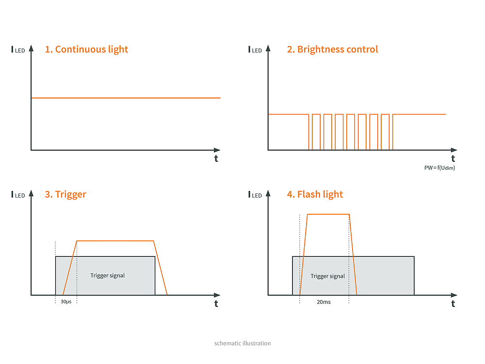
Operating modes of the internal controller
1. Steady light
Stable steady light with 24 VDC, the current is fixed depending on the respective lighting model.
2. Brightness control
The brightness can be adjusted via an analog control input between 1 V and 10 V with a max. resolution of 200 steps. Due to the PWM control with 3.8 kHz we recommend an exposure time of min. 5 ms.
3. Trigger
The trigger input is high active. From a signal level of approx. 5 V the illumination is switched on. Up to a signal level of approx. 1 V the illumination is off. The latency of the lighting device is about 20...30 μs.
4. Flash light
A flash is generated which is up to twice as bright as the continuous light. The flash is synchronous to the trigger signal with a max. possible flash time of 20 ms. If the trigger remains active for longer than 20ms, the light switches off automatically after 20ms. Frequencies up to 1 KHz are possible. As max. duty cycle we recommend 25%, as min. flash time 100 μs.
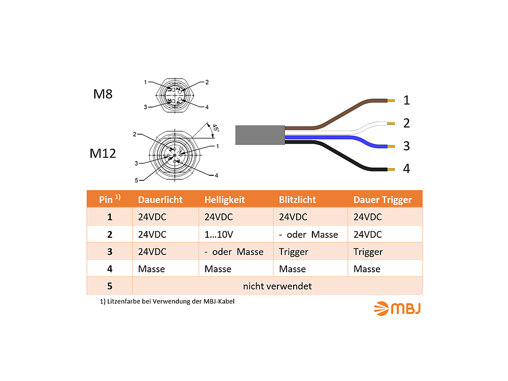
Connection of the cable controller & the integrated -s controller
The cable controller as well as the integrated LED controller (-s) offer four different operating modes.
The lights are connected and controlled via a M8 4-pin or M12 5-pin flange connector, depending on the version. The ringlight SRL-04 and the cable controllers are connected via a 4-wire cable with open ends.
The overview graphic shows the pin assignment to operate the lighting in the selected operating mode.
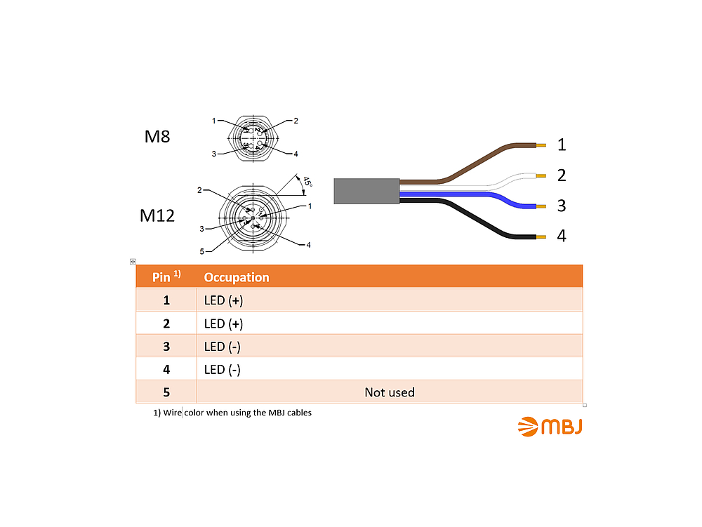
Connection w/o internal controller (-x)
All MBJ lights can also be purchased without internal controllers (-x), e.g. to operate them via an external controller. For the best possible control the -x devices have a direct LED access. For the selected operating mode, the correct current must then be set/controlled, the voltage then adjusts itself depending on the LED color.
As external controllers, e.g. the models of the CTR series are ideally suited.
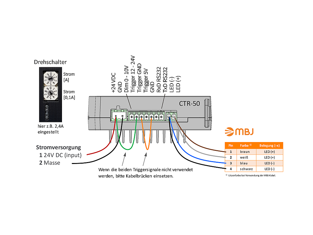
CTR-50 for steady mode with x- lights
The CTR-50 ensures constant brightness via uniform current control, which enables consistent recording quality.
The current, to be set via the rotary switches, depends on the number of installed LEDs as well as the LED color. This information is available in the specification or on type plate of the respective lighting.
The light can be switched on/off via trigger signals. If the trigger signals are not used (steady mode) a cable bridge must be set. Alternatively, the CTR-50 can also be set to continuous light mode via RS232 with the command "WM3" (save the setting with "EM"), then the cable bridges are not required.
The Flexlight series is only available in the -x version, for example, due to the possible illumination size and the slim design. With the CTR-50, the brightness of the Flexlights can be easily controlled.
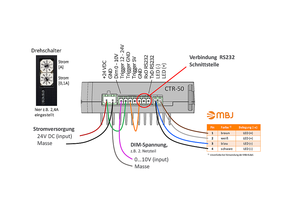
CTR-50 for brightness control with -x lights
The brightness can be controlled with the CTR-50 in 3 different ways, 2 of which require RS232 access. For all variants the CTR-50 is connected as for steady light.
1. Adjustment via the outer rotary switches
The current and thus the brightness can be reduced via the rotary switches in steps of 1A (upper switch) or 100mA (lower switch).
2. Percentage brightness
The current set at the rotary switches for steady light can be reduced in steps of 0...100% via RS232 using the command "WBxx" during operation. "WB30" e.g. corresponds to 30% of the current. "EB" saves the value in the CTR-50.
3. Additional DIM voltage 0...10V
The CTR-50 is connected via RS232 and the DIM voltage is applied with 10V. Read out the actual DIM level via "R2", subtract ~20 from it (voltage loss) and set it again with "WDxxx" (no preset value). Then save with "ED". Application example: "R2" reads 862, set new level with "WD840". Afterwards the brightness can be adjusted with the DIM voltage 0...10V.
A manual for the connection and details for the operation of the CTR-50 via RS232 is available here.
Terms Controller
Duty Cycle
The duty cycle describes the ratio of pulse duration (LED on) to period duration. The smaller the duty cycle (in %), the less the LEDs heat up and can therefore be operated with higher currents (more brightness) and have a longer service life. Basically, turn off the light as soon as it is not needed to maximize the operating time of the lighting.
Latency time of the LED lighting (switch-on behavior)
The latency time or typical LED switch-on delay describes the time needed to switch on the lighting from the arrival of the trigger signal to approx. 90% brightness. This is caused by capacitances in the electronics, the LED cable (the longer the cable the higher the capacitance and thus the flash delay) and the LED itself.
Boost/ Stobe vs. Flash/ Flash Mode
LEDs can be significantly overcurrented for short periods of time - even more than 400% depending on the LED and duty cycle - this is called Boost mode at MBJ. This higher current leads to a significant increase in brightness in contrast to the -s flash mode. In the -s controller's flash mode, the LEDs are also supplied with higher currents than in continuous mode, but lower than in boost mode. The flash mode leads to up to a doubling of the brightness yield and can be operated with slightly longer duty cycles than the boost mode e.g. via the CTR-51.